
The physical principle involved can either be by utilizing eddy current effects or magnetic induction effects. With eddy currents the change in impedence due to eddy currents induced is used.
The principle of magnetic induction is similar to that of transformer. When there is a change to the amount of ferromagnetic material under the search head by the presence of reinforcing bar or other metal object, there is an increase in the field strength.
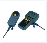
The equipment used is called Coverometer. Which are available with both concepts the eddy currents based and the magnetic induction based coverometer.Typically they comprise of a search head, meter and interconnecting cable.
Applications
- Quality control to ensure correct location and cover to reinforcing bars after concrete placement.
- Investigation of concrete members for which records are not available or need to be checked.
- Location of reinforcement as a preliminary to some other form of testing in which reinforcement should be avoided or its nature taken into account.
- Location of buried ferromagnetic objects other than reinforcement, e.g. water pipes, steel joints, lighting conduits.
- Locate in structures such as reinforcement and cable ducts
- Measure the cover to the reinforcement
- Estimate the size of the reinforcement
Codes
- BS4408 part1
Methodology
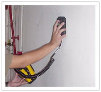
Before using the coverometer suitable calibiration technique should be followed according to the code. If different heads are to be used at different locations calibiration should be carried out for all head individually. This is then kept over the concrete surface and readings are noted. The readings are taken on sampled points over an area so that the mapping accuracy can be obtained according to the needs.
Limitations
- It is very slow and labour intensive.
- The results are affected by the presence of more than one reinforcing bar in the test area, by laps, by second layers, by metal tie wires and by bar supports.
- For maximum accuracy it has to be calibrated for the concrete used in the structure to eliminate the influence of iron content of the aggregate and cement used.
- The method is unsuitable in the case of closely packed bar assemblies.
- The accuracy is reduced if rough or undulating surfaces are present,
- Calibrated meter scales are generally valid for a particular grade of reinforcing steel only.
- For accurate measurement of cover and size, the bar has to be both straight and parallel to the concrete surface.
- Where significant corrosion to reinforcement has occurred misleading cover readings are likely to be obtained.
- Interference effects will occur in the neighbourhood of metallic structures of significant size.