
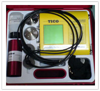
The equipment consists essentially of an electrical pulse generator, a pair of transducers, an amplifier and an electronic timing device for measuring the time interval between the initiation of a pulse generated
at the transmitting transducer and its arrival at the receiving transducer.
The velocity of an ultrasonic pulse is influenced by those properties of concrete which determine its elastic stiffness and mechanical strength. Hence Each material has typical ultrasonic pulse velocities. These velocities can be correlated with the material properties. Comparatively higher velocity is obtained when concrete quality is good in terms of density, uniformity, homogeneity etc
Applications
- Determination of the uniformity of concrete in and between members measurement
of changes occurring with time in the properties of concrete - Correlation of pulse velocity and strength as a measure of concrete quality.
- Determination of the modulus of elasticity and dynamic Poisson’s ratio of the concrete.
Codes
- IS: 13311
- BS 1881-203
- EN 12504-4
- ASTM C597
Methodology
- Preparing for use: Before switching on the ‘V’ meter, the transducers should be connected to the sockets marked “TRAN” and ” REC”. The ‘V’ meter may be operated with either:
- The internal battery,
- An external battery or
- The A.C line.
- Set reference: A reference bar is provided to check the instrument zero. The pulse time for the bar is engraved on it. Apply a smear of grease to the transducer faces before placing it on the opposite ends of the bar. Adjust the ‘SET REF’™ control until the reference bar transit time is obtained on the instrument read-out.
- Range selection: For maximum accuracy, it is recommended that the 0.1 microsecond range be selected for path length upto 400mm.
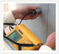
- Pulse velocity: Having determined the most suitable test points on the material to be tested, make careful measurement of the path length ‘L’™. Apply couplant to the surfaces of the transducers and press it hard onto the surface of the material. Do not move the transducers while a reading is being taken, as this can generate noise signals and errors in measurements. Continue holding the transducers onto the surface of the material until a consistent reading appears on the display, which is the time in microsecond for the ultrasonic pulse to travel the distance ‘L’™. The mean value of the display readings should be taken when the units digit hunts between two values.
Pulse velocity=(Path length/Travel time)
- Separation of transducer leads: It is advisable to prevent the two transducer leads from coming into close contact with each other when the transit time measurements are being taken. If this is not done, the receiver lead might pick-up unwanted signals from the transmitter lead and this would result in an incorrect display of the transit time.
Limitations
- Moisture content significantly affect the readings.
- The temperature of testing should be between 10C to 30C for good results.
- Minimum path length is prescribed in the codes they should be followed
- Reinforcing bars significantly increase the pulse velocity they should be taken care.
- Hetrogenities cause variations in pulse velocities.